DDS crystal sub PCB installed internally
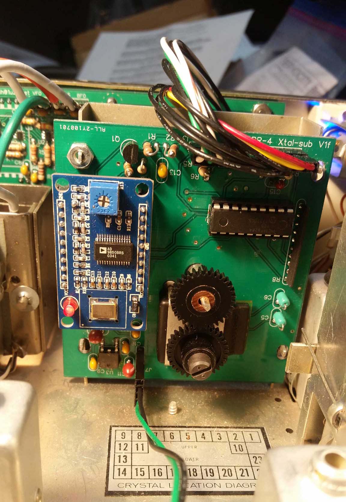
Internal installation of DDS crystal-sub
DDS Replacement of Crystal-Bank
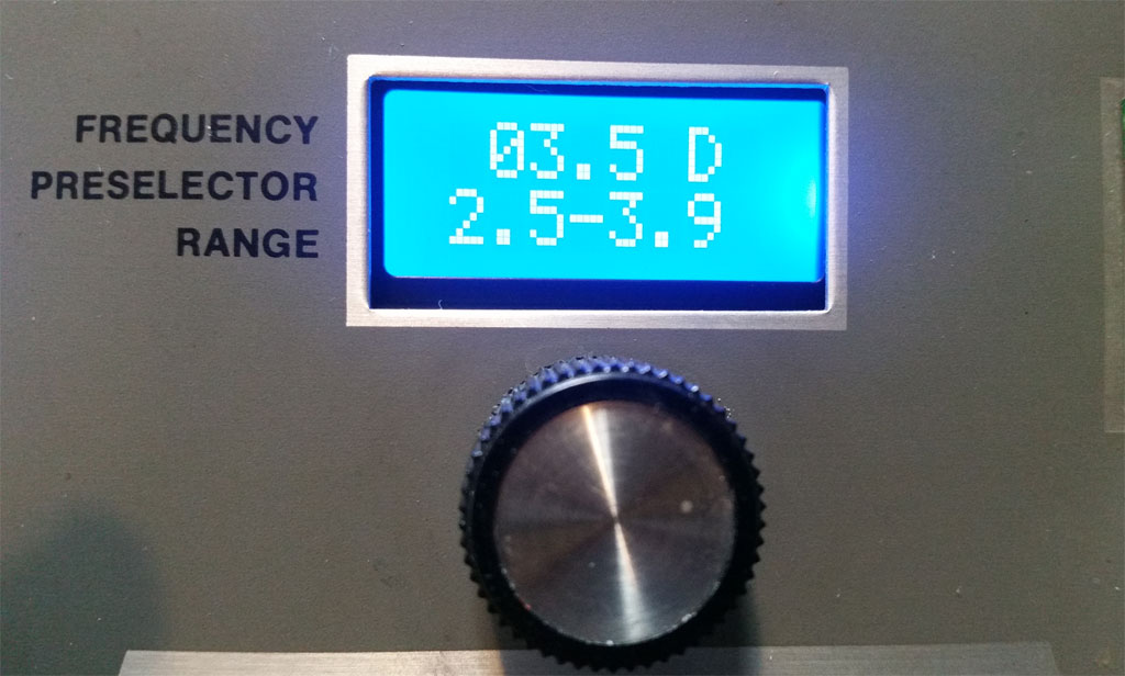
The SPR-4's original method of selecting bands was by selecting crystals in a bank of 23 crystals. Each crystal was used by the first mixer to select a 500KHz band. To achieve full coverage, from 200KHz to 30 MHz, would require 60 sockets and a 60 position band-selector switch. Drake only provided 24. Moreover, each crystal was slightly off-frequency (normal manufacturing tolerance) and this required recalibration of the receiver's dial with every switch to a new band. DDS chips and modules using them have become surprizingly inexpensive. A DDS chip can be easily programmed to put out any frequency within it's range. This makes it a good choice to replace the SPR-4's crystal bank and to generate all the frequencies required to enable to SPR-4 to receive on all bands from 200 KHz to 30 MHz. This replacement for the SPR-4's crystal bank has its own LCD display which displays the frequency-band that is currently selected, plus the associated preselector settings. This LCD-display and the DDS chip are both controlled by a PIC 16F628A microprocessor. Initially, I put the DDS, the encoder and the microprocessor on a PCB of the same size as the original crystal-bank PCB. The original selector knob and shaft drives the new encoder to select bands. The associated "band-selection" LCD display is mounted in and is read through the same window in the front panel where the band-selection dial was previously mounted and read. The operator still selects the band to be received by turning a knob. This selection is conveyed to the microprocessor by an encoder which is monitored and read by the microprocessor. In the internal installation, which is shown at left, the selection knob is the original knob that turned Drake's 24 position switch. The switch wafer was removed with the crystal socket PCB, and replaced by my PCB with the DDS module and an encoder. Gears on the encoder and the switch shaft are now driving the selection. The mechanical stop on the switch shaft is gone and the knob will go around forever. The microprocessor program keeps the selections going up until the 29.5MHz band is reached or, down until the 200KHz band is reached. So, the mechanical stop has been replaced by an "electronic" stop. Removal and replacement of the crystal-bank PCB, its switch and its associated dial were determined to be too complex for most users. For this reason, a version is being designed which puts the DDS module, as well as the new LCD Frequency-Display (used in lieu of the original tuning dials,) into a box that sits on top of the receiver.