These dials have not been removed.
The LCD is shown mounted behind the dials.
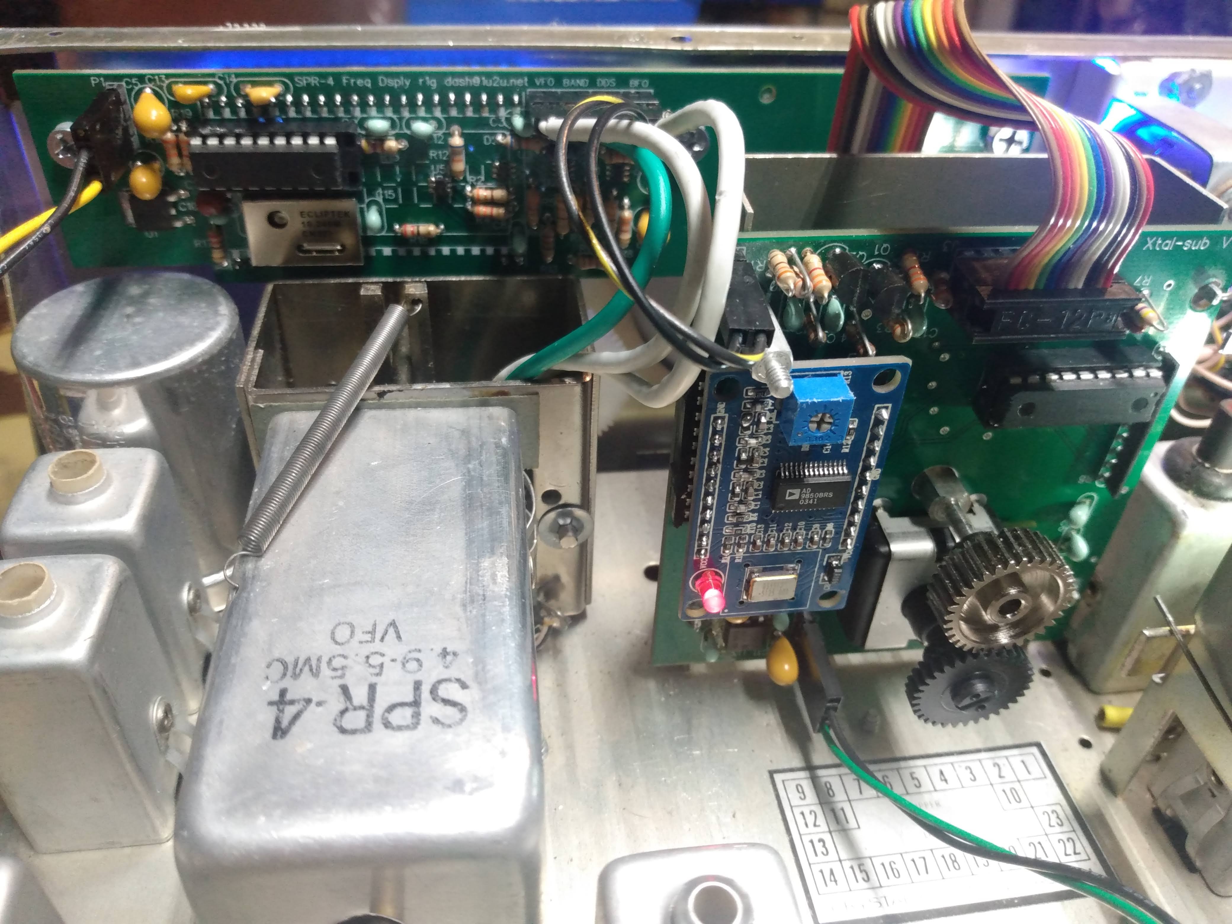
Cables connecting oscillator signals to the
LCD-display PCB mounted on the front-panel.
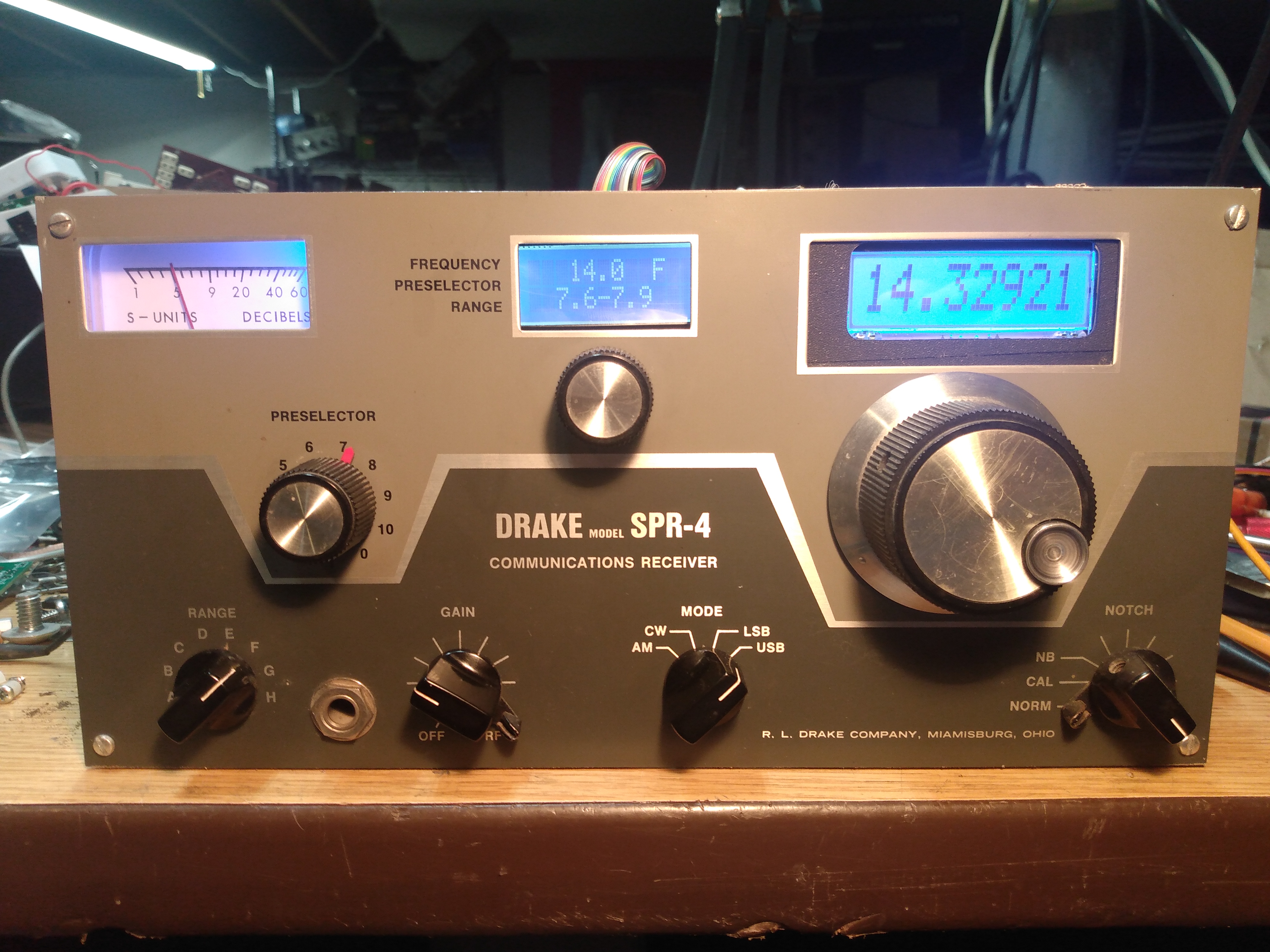
The dials have finally been removed.
The LCD is shown mounted in the window.
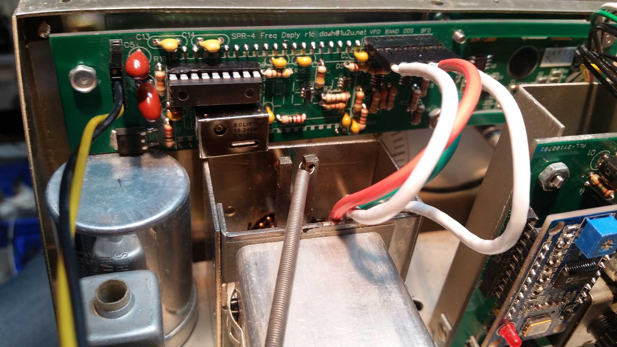
This shows both PCB boards, viewed from
the rear of the receiver.
Final changes to the LCDs and PCBs
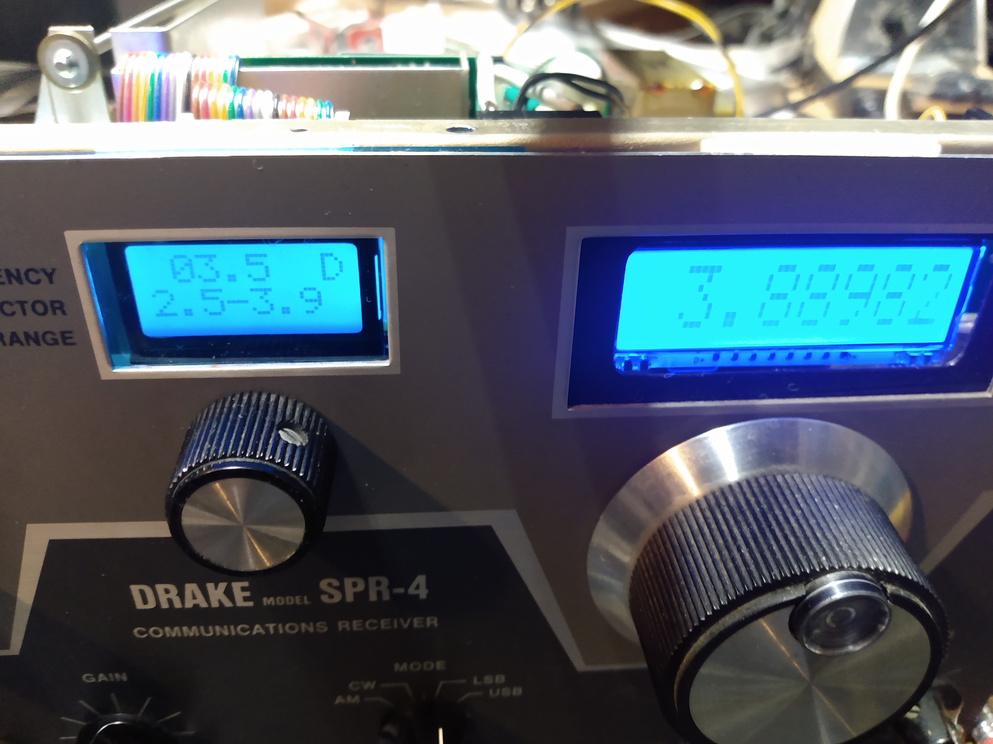
Freq diplay centered and band LCD changed
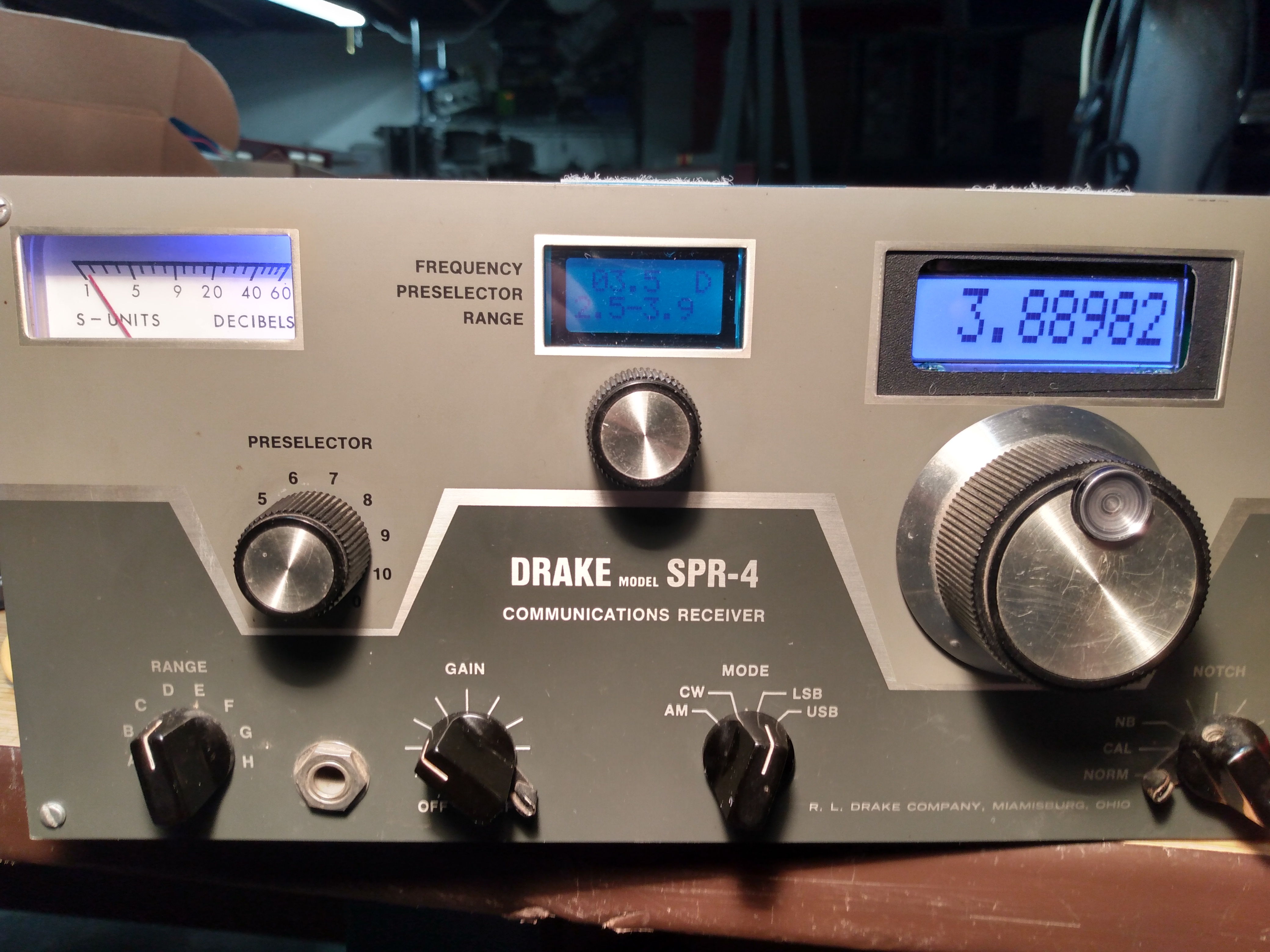
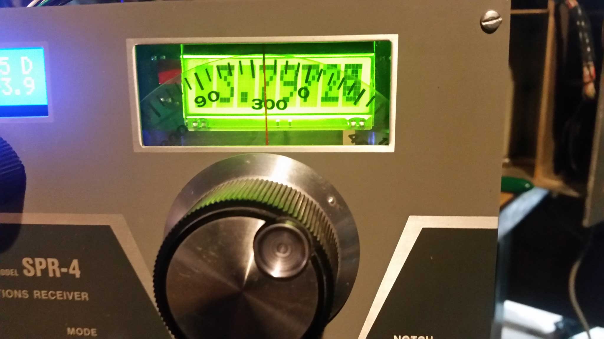
Closeup of LCD displays
LCD Frequency Display for the SPR-4
The Drake SPR-4, being one of the first solid-state HF receivers, is one of a very few solid-state models that lack a digital frequency display. The PTO and the gear-driven dials are much better than variable capacitors and dial-cord driven scales and dials. But even the SPR-4's gear-driven dials aren't a good substitute for a true digital frequency display.
The digital frequency display described here is not a simple counter that subtracts the nominal IF frequency from a frequency counter that measures the first local-oscillator. Instead, this frequency-counter is effectively four counters, each one measuring a different oscillator used in the dual-conversion superhet process, including the BFO whenever it is turned on. The four frequencies are then added/subtracted as necessary to yield the actual received frequency. All these measurements and the arithmetic happen about 5 times per second. The display is very much alive. You can even meaure warm-up drift which, in the SPR-4, is very slight.
The accuracy of the frequency-display is now totally dependent on the time-base of the counter. The time-base it uses is a temperature-controlled and temperature compensated crystal oscillator: a TCXO. It is adjustable and it is adjusted during final testing of the Frequency-Counter by getting WWV to be on zero-beat while the Frequency-Display readout says "5.00000." Band-changes no longer affect the accuracy of the frequency readout. The counter's time-base determines the accuracy of everything.
This LCD Frequency-Display gets the four oscillator signals through a cable with four shielded cables. Each of these four shielded cables must be connected, in the underside of the SPR-4, to a point that has an oscillator's signal. Fortunately, the SPR-4 had four, oscillator pick-off points that are somewhat low-impedance in order to tolerate the additional loading of the coax cable and the input circuitry of the LCD Frequency-Display. The ends of the coax cables are soldered to the pick-off points during installation. These coax cables are short and must be kept short, in order to minimize this loading and avoid impairment of the SPR-4 functions and performance.
The original intent was to mount the LCD Frequency-Display in the window where the dials had been mounted. In the picture of the prototype, shown here at left, you can see the LCD Frequency-Display mounted behind the dials. The original dials need to be removed, so as to not interfere with the visibility of the new, digital display. I did not want to remove the gear-driven dials from the SPR-4 and I was worried about requiring other people to remove these dials. So a decision was made to offer this product in an external box that sits on top of the SPR-4. The short coax cables are passed through the hole in the SPR-4's top cover that was originally intended for use with their loop antenna.
Even with 100X improved resolution there is still no need for the SPR-4's original recalibration scheme. With this new, counter-based system, the only source of error is the single, common time-base for the four counters. The time-base has long-term stability of 2ppm per year. This oscillator is adjustable to reduce initial error to zero.
The photo at the left shows the Freq_Display PCB mounted internally, on the front panel. This view looks toward the front-panel from over the rear of the chassis. You can see the PTO in the foreground in the middle of the picture. On the right end of this view you can see part of the DDS replacement for the Drake crystal bank PCB.
In this view, the dials are hidden by this Freq-Display PCB, because they are sandwitched between the front-panel and this PCB. The dials would need to be removed for a permanent internal installation, which is why I have instead opted to offer the SPR-4 Freq-Display in an external box to sit in the top of the receiver. The colored coax signal cables would be passed through the hole in the top cover to the external box.
First full installation - - 12 December 2020
This next series of pictures shows my first full replacement of the dials by the LCD display. The PCB carries the LCD displays for both the DDS Crystal-substitute and the frequency readout. I still have some small changes to make. The frequency LCD is not centered in the window. The Crystal-sub's LCD is too far back behind the window. The frequency LCD needs some kind of bezel around it to hide the receiver's guts behind it. I need to decide if the displays should be black characers on a blue background or white on a blue background.
But it seems to be working perfectly. The Crystal-sub uses the original rotary-switch detent mechanism but with the original switch wafer removed and the stop removed. So now it turns continuously, forward and backward, and through two gears it drives an encoder that selects which band we want.
More later.
Final Configuration - 23 January 2021
I've moved the frequency display to it's final, centered position. I've changed the band display LCD and centered it too. These are cosmetic changes that make it look as good as I can reasonably achieve. What about performance? Everything seems to be working well, but I will double check the levels going into the counter a last time. Birdies??? Yes there are a few birdies, but not objectionable. I've seen a couple of strong birdies. I will continue looking and logging as I find them. I have not yet seen the numerous weak birdies I was afraid of. The big question is how to sell this product. It takes considerable modification to the SPR-4, much more than my earlier R-390A product required. And tapping into the signals that the counter needs to do its job is messy. The construction of the SPR-4 is tight and the tap points are buried in congested areas on PCBs that are mounted on edge and hard to reach. It will require considerable skill and care on the part of the technician to get this installed properly. I'm not sure how many SPR-4 users are going to have the requisite skill. Please contact me if you think you are a good candidate..