Cables connecting oscillator signals
to the LCD-display PCB.
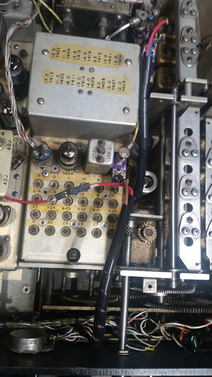
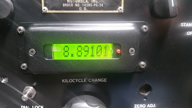
LCD Frequency Display
The original mechanical frequency-readout is always wrong. It is a gear-driven mechanism tied to the PTO tuning shaft. It only "predicts" the frequency the receiver is supposed to be tuned to. There are several sources of error that cause it to be wrong. The first-converter uses a 17MHz crystal which is never exactly 17MHz but differs by a slight amount which is a normal, allowable manufacturing-tolerance. The second-converter uses a bank of crystals to enable band selection. Each crystal differs from its ideal frequency by a small percentage which is a normal manufacturing tolerance. This "error" is different for every crystal and every associated band. This is the reason why the R-390A must be recalibrated after every band switch. The receiver's 100KHz crystal calibrator is used as a work-around method to accomodate these and other sources of error. Even after recalibration there are still errors causing the mechanical readout to be inaccurate. The PTO is unavoidably nonlinear, although the nonlinearity can be minimized with careful adjustment during overhaul. The nonlinearity can never be totally eliminated and it increases with age until eventually the PTO cannot meet its specification of maximum allowable nonlinearity. The PTO's endpoints must likewise be adjusted during overhaul and with age all PTOs eventually exceed their endpoint adjustment tolerance. The BFO is not included in the mechanical frequency readout. Thus, when the BFO is turned on it does not affect the indicated frequency. This is a problem during SSB tuning, as the indicated frequency does not reflect the frequency of the SSB signal that is tuned in. All of the mechanical readout's errors can be avoided by replacing it with an electronic readout that is driven by a frequency counter system that continuously measures all the frequencies used in the receiver and combines them mathematically to calculate and display the actual received frequency. The combined output of the counters is displayed on an LCD display which is updated approximately 4 times per second. This update rate allows two more digits to be displayed than the mechanical display had, i.e., resolution is now to the nearest 10Hz, 100X better than before. Even with 100X improved resolution there is still no need for the R-390A's original recalibration scheme. With this new, counter-based system, the only source of error is the single, common time-base for the four counters. The time-base is a temperature-controlled and compensated crystal oscillator with long-term stability of 2ppm per year. This oscillator is adjustable to reduce initial error to zero. A pushbutton is provided to enable reading the BFO frequency. Pressing the small red button at the right end of the LCD readout, changes the counter system to display ONLY the BFO's frequency, for as long as the button is pressed. This enables positioning the BFO accurately within the passband of the selected mechanical-filter. This facilitates optimizing the BFO frequency setting for interferance and noise conditions. The BFO signal is buffered and provided to the LCD Frequency Display by another product sold here, the Product-Detector product. The LCD Frequency-Display requires our Product-Detector in order to operate properly. Everything is fully assembled. It just needs to be installed in the R-390A. Only two connections are soldered. The wires from the original panel lamps are unsoldered and spliced onto a small power-cable (supplied) which will be plugged into the main PCB. All other connections are coax. Three small boards mount onto the three coax BSM jacks, J415, J221 & J217. These small boards are buffer circuits which sample the oscillator signals without loading them or reducing their amplitude. The main PCB has the LCD on it and the microprocessor/counter circuit. This board is already mounted in a freshly-painted bezel/escutcheon. You just need to remove the original bezel/escutcheon and the Veeder/Root mechanical display, to make room for the new ones. You can save your original parts in case you ever want to restore your receiver to original/unmodified-condition. Now here's the bad news. I built over 60 of these kits but I'm now out of connectors and I can't find any more at a reasonable price. So, I have to quit. Each kit uses three Kings KM59-25 connextors. These are generally called BSM connectors and are obsolete. I was lucky and found 185 of them on eBay several years ago. I bought all the seller had. The datecode on the packages was 1987. My assumption is that this was the date of the last production run. I can now only find these connectors at companies that want to sell them to military and aircraft equipment repair facilities for $10-$17 each, in quantity, which is a ridiculous price. Plus, as of August 2020 I'm burned out from building these kits for so long. Each kit takes about 8 hours to prepare. If someone can find a source of these connectors at a reasonable price, ~$1 each, please let me know. Maybe I could be pursuaded to make a few more kits.