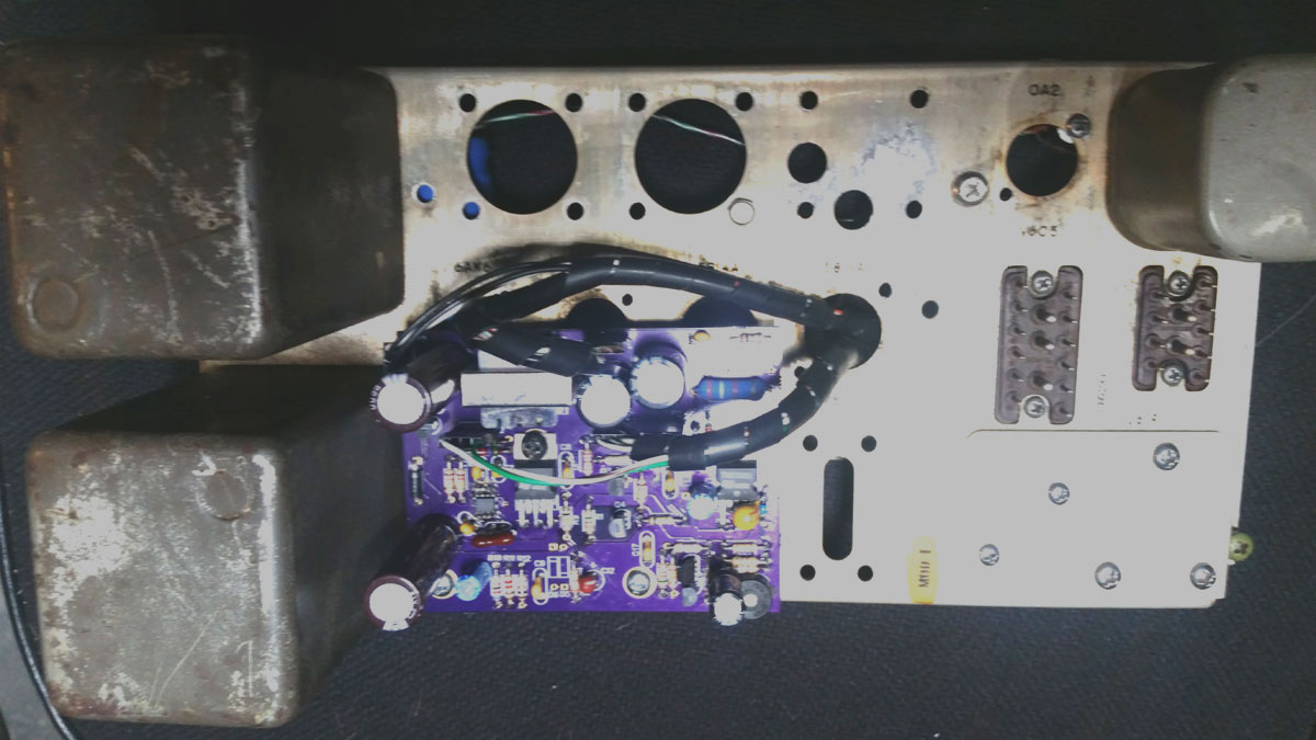
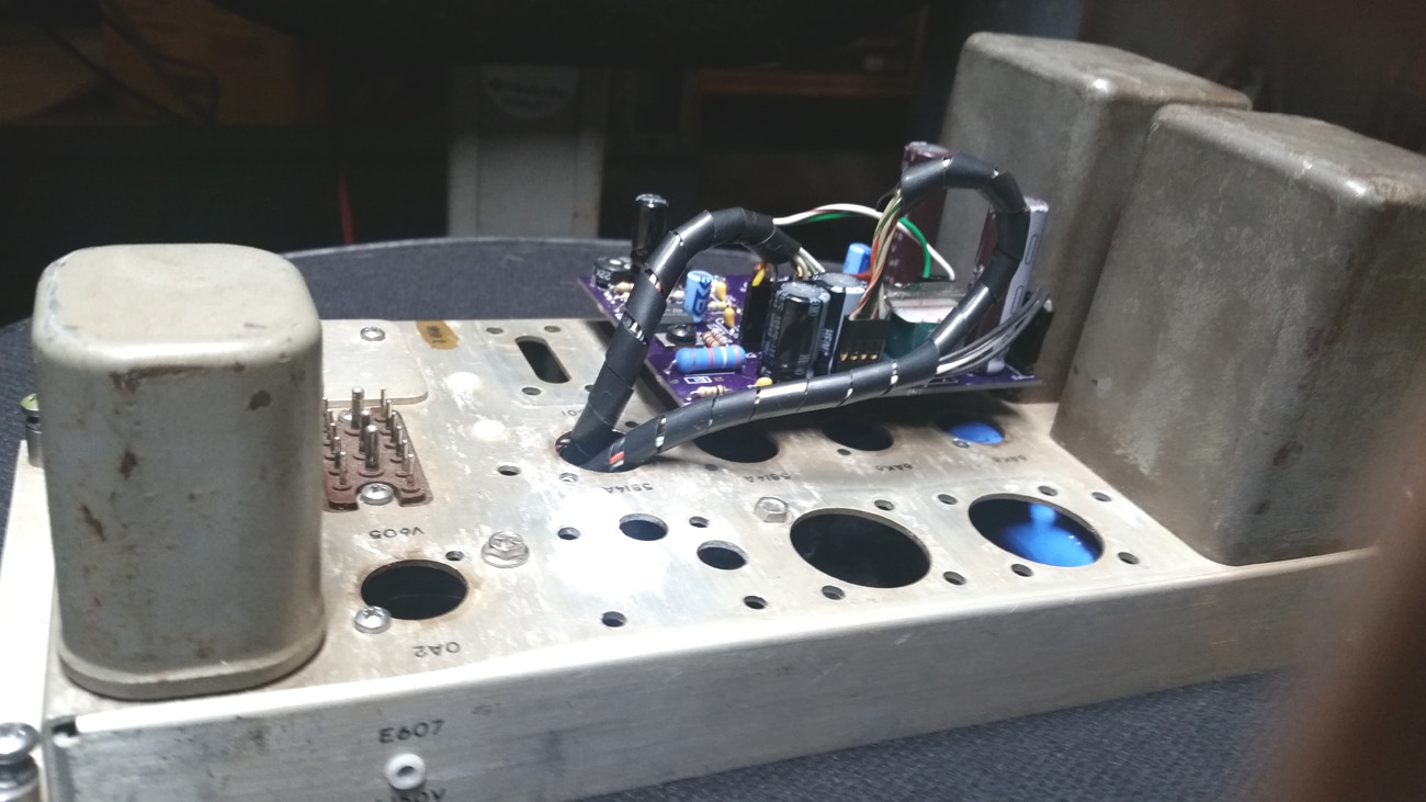
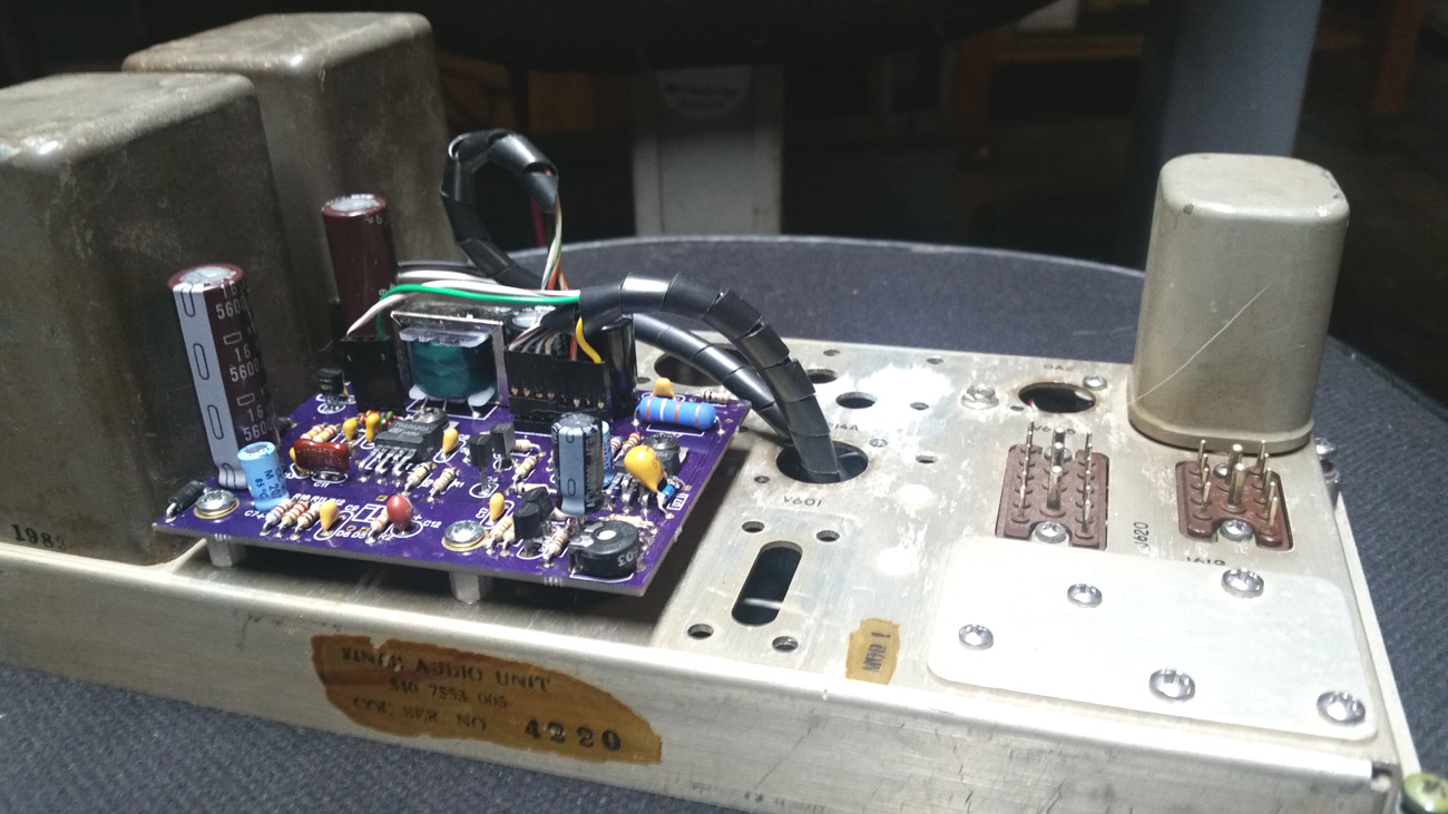
Early prototype, 2016
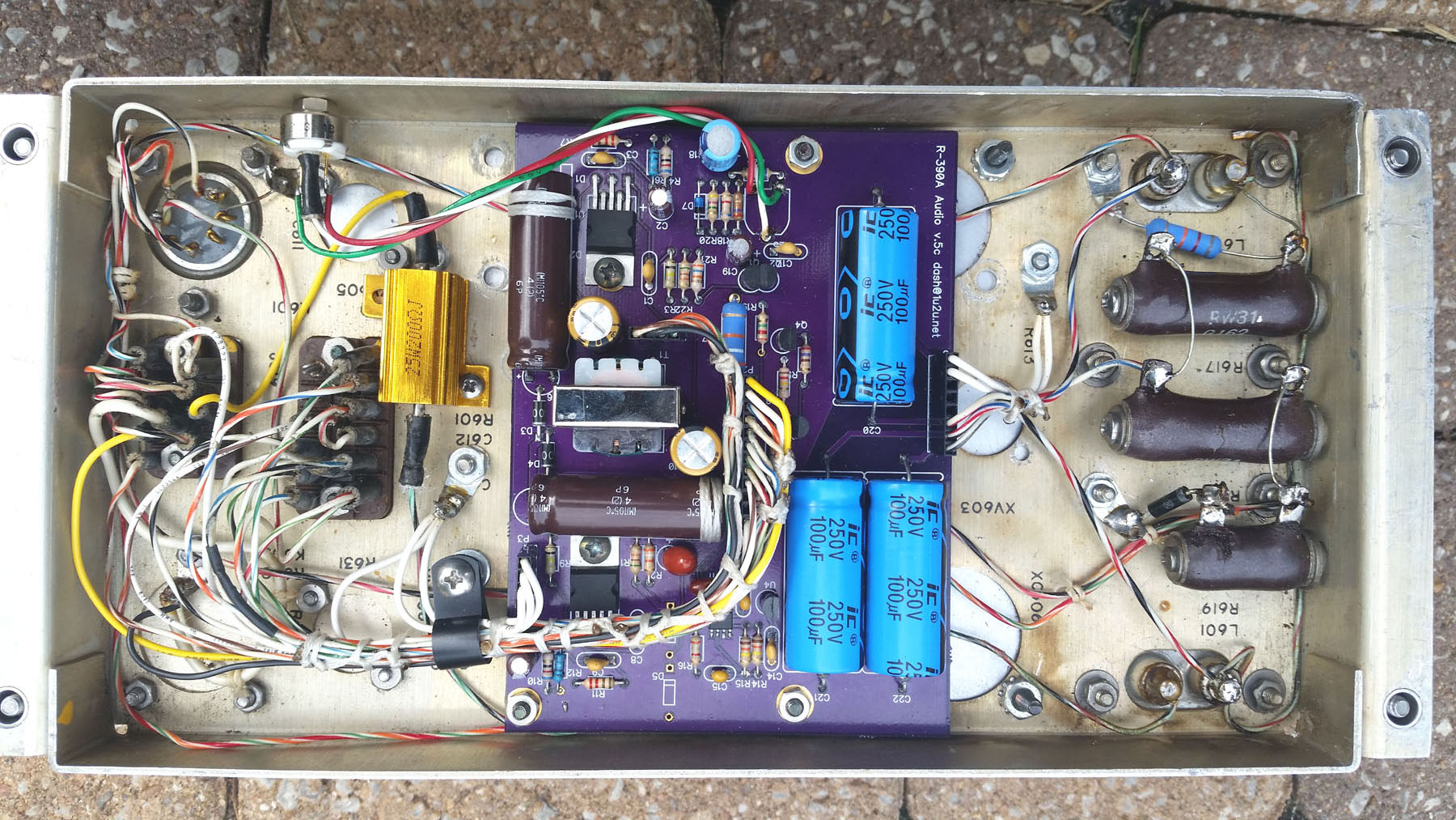
2017 production
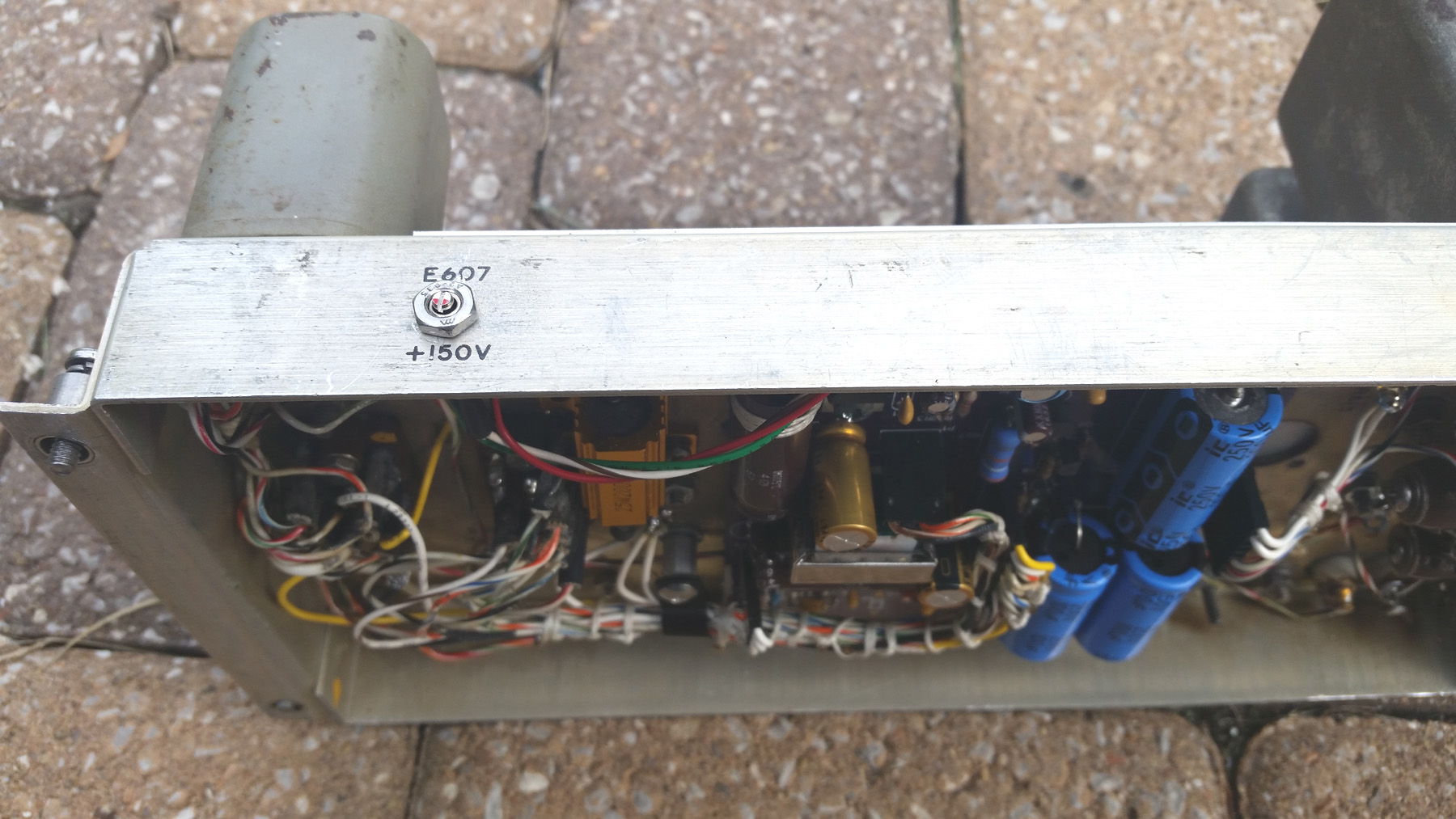
PCB underneath, 3KHz filter, squelch pot
Conversion of the Audio-module to solid-state
The Audio-module has 5 tubes and sits directly below the IF-module. Two of the Audio-module's tubes, the 6AK6s, generate considerable heat. They also generate some distortion. Their output transformers restrict the frequency-range of the audio and cannot drive a 4- or 8-Ohm speaker directly. Collins designed a squelch for the Audio-module, but it was omitted due to cost constraints and very, very few surplus R-390A's have the squelch. All of the above shortcomings can be eliminated by replacing the original tube-design with a solid-state version. There are inexpensive ICs that make the design simple. The original output transformers are eliminated, although the "LINE" output transformer is replaced with a smaller, PC-board mounted 600 Ohm output-transfomer to accomodate the front-panel's "LINE" audio level meter and to provide for connections to external amplifiers, recording devices, RTTY and FAX equipment, and other applications. Externally, you can't tell that the R-390A's Audio-module has been changed. The R-390A simply sounds better and works better. The squelch function, that was included in the R-390A's original design but omitted from its production, is included in my conversion because it required only a few, inexpensive components. The R-390A's standard power-switch includes a sixth position, the "SQUELCH" position, which is blocked by an easily removable washer under the power-switch's mounting nut. My squelch circuit is driven from the AGC line. Any signal that is capable of moving the carrier-meter's needle can open the squelch. It even works for SSB signals. The "NARROW" audio filter was 800Hz in the original, Collins design. Very few R-390A users use it today. I found an article by Dallas Lankford who claimed that, in his experiments, a 3KHz audio filter was just as effective as a good synchronous-detector for receiving AM under heavy-fading conditions. Apparently, the loss of carrier or portions of sidebands within the IF passband can create high-frequency audio noise components that should not be present because they exceed the passband. By filtering out these noise components with a good, sharp low-pass audio filter, much of the associated distortion can supposedly be eliminated. So, I included a 3KHz filter in my design, much better than the one Dallas was recommending, and it does seem to benefit badly-fading AM signals. My new filter is still selected by the front-panel's original "WIDE NARROW" switch. While the circuit-board for this solid-state conversion is simple and inexpensive, the process of rebuilding and rewiring the Audio-module is not. The tube sockets, the filter-capacitors' sockets, the output transformers, the 800Hz audio filter and numerous other components must be removed before the new circuit-board can be mounted on the chassis. Then there is the big job of rewiring everything to connect to the new circuit-board. It is a daunting project with many opportunities for error. My hope is to find skilled technicians who love the R-390A and are willing to sell conversions using my PC-board. The eliminaton of the Audio-module's tubes and their associated heat lets the IF-module run much cooler. This change, together with the elimination of the Current-Regulator in the IF-module, makes the IF-module remarkably cool and comfortable. The Spring 2017 redesign of the audio PCB puts the PCB underneath, inside the chassis, and adds the B+ filter capacitors to the PCB. Now, nothing is above the chassis and an aluminum plate is added to the topside to cover all the empty holes and improve the appearance. The PCB connectors are still the same, 0.025"sq pins on 2.54mm centers that are commonly seen on computer motherboards. With the PCB connectors now on the same side of the chassis as the J619 and J620 connectors' wiring, the wires are easier to route and can be laced together into a neat harness. This PCB allows movement of the squelch potentiometer. I removed the 150V testpoint, enlarged its hole slightly, and mounted a small trimpot in its place. You can see this new pot in the bottom picture. This makes the squelch adjustable without having to turn the receiver upside down. Now the squelch is adjustable, with a small screwdriver, on the receiver's left side. If you mount your receiver inside a cabinet, squelch adjustment may still be a problem.